Raspberry PI Spiderbot
Wolfgang Fahl
| OsProject | |
|---|---|
| id | PI-Q-Robot |
| state | |
| owner | BITPlan |
| title | Raspberry PI controlled Quadruped Robot with 3D Simulator |
| url | https://github.com/BITPlan/PI-Q-Robot |
| version | 0.0.1 |
| description | |
| date | 2019-08-07 |
| since | |
| until | |
Click here to comment see Self Driving RC Car
Inspired by the Arduino Project below we'd like to create a Raspberry PI version as in https://github.com/yasaspeiris/aragog
Video
Simulator
Video[edit]
Calibration[edit]
Restful interface[edit]
http://<baseurl>/servo/<servoid>/<angle> will set the angle of a single servo
Servo numbering scheme[edit]
This is the default numbering schema as configured in the software. If your servos are mounted or cabled differently you might want o adjust the code a accordingly
| ServoId | Leg | Extrimity | Inverted |
|---|---|---|---|
| 0 | 1 | Coxa | |
| 1 | 1 | Femur | x |
| 2 | 1 | Tibia | x |
| 3 | 2 | Coxa | |
| 4 | 2 | Femur | x |
| 5 | 2 | Tibia | x |
| 6 | 3 | Coxa | |
| 7 | 3 | Femur | |
| 8 | 3 | Tibia | |
| 9 | 4 | Coxa | |
| 10 | 4 | Femur | |
| 11 | 4 | Tibia |
Calibration Range[edit]
| Extremity | Servo Angle | Position | Direction | Range |
|---|---|---|---|---|
| Coxa | 90 | 45° | left to right | 0°-180° |
| Femur | 90 | Flat | up to down | 0°-180° |
| Tibia | 90 | Flat | down to up | 0°-180° |
Relevant source code[edit]
class Spider:
    """ I am a quadruped spider with four legs consisting of coxa, femur and tibia each"""
    def __init__(self):
        self.fl = Leg(0, 0,  1,  2)
        self.fr = Leg(1, 3,  4,  5)
        self.rl = Leg(2, 6,  7,  8)
        self.rr = Leg(3, 9, 10, 11)

...
class Leg:
    """ I am a single leg of the spider consisting of coxa, femur and tibia"""
    def __init__(self, legId,coxaId, femurId, tibiaId):
        self.legId=legId
        self.coxa = Extremity('coxa', coxaId)
        self.femur = Extremity('femur', femurId,legId<2)
        self.tibia = Extremity('tibia', tibiaId,legId<2)

...
class Servo:
    """ I am a single Servo motor """
    def __init__(self, id,inverted=False):
        self.id = id
        self.inverted=inverted

    def setAngle(self, angle):
        self.angle = angle
        trueAngle=180-angle if self.inverted else angle
        if kit is not None:
            kit.servo[self.id].angle = trueAngle
        return trueAngle
Parts[edit]
| # | picture | part | example sources | documents | ~ price | |
|---|---|---|---|---|---|---|
| 1 |  |
Raspberry PI 3 B+ | Raspberry PI 3 B+ | en | 35 € | |
| 2 |  |
microSD Card | SanDisk 16 GB | 7 € | ||
| 3 |  |
Raspberry PI Camera | 1080 p Camera Module | 23 € | ||
| 4 |  |
DC/DC Converter 12 V-> 5V | 12 V->5 V Converter Module | 7 € | ||
| 5 |  |
Micro USB Connector | Delock USB 2.0 Micro USB | 6 € | ||
| 6 |  |
3D Printed Parts: Coxa, Tibia, Femur, Hinge | parts from regishu's design | |||
| 7 | 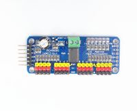 |
Adafruit PCA9685 16 channel PWM controller | PCA9685 | 6.5 € | ||
| 8 |  |
set of small screws | set of small screws | 8.5 € | ||
| 9 |  |
12 x MG90S | 12 x MG90s | 42 € | ||
| Total | ~ 135 € | |||||
| a | 
|
Breadbord Kit | MB102 Breadbord Kit | 7 € | ||
| b | 
|
Ulrasound Sensor | 5 x HC-SR04 + Cables | 10 € |


Assembly[edit]
- Legs and hinges are connected with 1.4x5mm screws
- Legs and servos are connected with 1.7x6mm screws


We use the raspberry base from https://github.com/yasaspeiris/aragog/blob/master/3d%20printed%20parts/base.STL

Leg Test[edit]
sudo python3 testadafruit.py 0 1 2 3 0

sudo python3 testadafruit.py 0 1 2 3 90

sudo python3 testadafruit.py 0 1 2 3 180

testadafruit.py[edit]
# Test Adafruit
# WF 2019-07-09
import sys
import time
from adafruit_servokit import ServoKit
kit = ServoKit(channels=16)

#
# set the given angle for the given servos
#
def setAngle(servos,angle):
  print (angle)
  for id in servos:
    kit.servo[id].angle=angle
  time.sleep(0.3)

# Test Servo Software
servos=[]
args=len(sys.argv)
fromangle=0
toangle=180
step=1
if args>1:
  for port in range(1,args-1,1):
    servos.append(int(sys.argv[port]))
  anglestr=sys.argv[args-1]
  if "-" in anglestr:
    parts=anglestr.split("-")
    fromangle=int(parts[0])
    toangle=int(parts[1])
  else:
    fromangle=int(anglestr)
    toangle=fromangle
else:
  servos.append(0)
  servos.append(1)
  servos.append(2)

if fromangle!=toangle:
  try:
    while True:
      for setangle in range(fromangle,toangle+step,step):
        setAngle(servos,setangle)
  except KeyboardInterrupt:
    print("Keyboard interrupt")
else:
  setAngle(servos,fromangle)
Evolution of Base[edit]
Since we'd like to use a Raspberry PI we couldn't use the orignal Base by regishu. Trying the one from https://github.com/yasaspeiris/aragog also did not work since our raspberry PI case had a different size. So incrementally a new design was created:

The problems mentioned further below led to this design:

Legtest 2[edit]
The three parts of a leg have been connected to the ports 10,11 and 12 and then the test was started with:
sudo python3 testadafruit.py 10 11 12 60-120
Wiring[edit]
Breadboard - style wiring before designing a proper holder:

In this state of affairs:
- the power input of the raspberry is blocked by a servo - needs to be moved by at least 13 mm
- the corner hinges are to close to the corners of the servo holders
- the pivots to be used for the next level are blocking e.g. the usb connectors