Raspberry PI Spiderbot: Difference between revisions
| Line 49: | Line 49: | ||
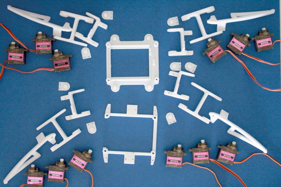
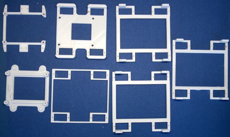
You might want to make sure that you print your parts with sufficient infill - I used 75%. | You might want to make sure that you print your parts with sufficient infill - I used 75%. | ||
[[File:SpiderBotParts-IMG_0028.jpeg| | [[File:SpiderBotParts-IMG_0028.jpeg|960px]] | ||
== Example for broken part == | == Example for broken part == | ||
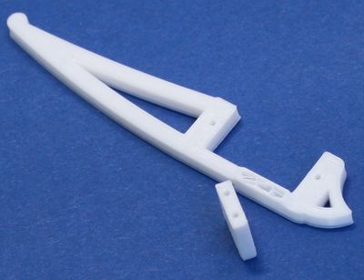
This part was printed with {{Link|target=Cura}}'s default infill an broke off: | This part was printed with {{Link|target=Cura}}'s default infill an broke off: | ||
Revision as of 11:28, 25 July 2019
Inspired by the Arduino Project below we'd like to create a Raspberry PI version as in https://github.com/yasaspeiris/aragog
Video
Links
- Spider robot(quad robot, quadruped)-MG90 regishu 2017
- https://www.hackster.io/yasaspeiris/raspberry-pi-powered-quadruped-bbb68b
- https://github.com/yasaspeiris/aragog
Parts
| # | picture | part | example sources | documents | ~ price | |
|---|---|---|---|---|---|---|
| 1 |  |
Raspberry PI 3 B+ | Raspberry PI 3 B+ | en | 35 € | |
| 2 |  |
microSD Card | SanDisk 16 GB | 7 € | ||
| 3 | 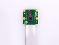 |
Raspberry PI Camera | 1080 p Camera Module | 23 € | ||
| 4 |  |
DC/DC Converter 12 V-> 5V | 12 V->5 V Converter Module | 7 € | ||
| 5 |  |
Micro USB Connector | Delock USB 2.0 Micro USB | 6 € | ||
| 6 |  |
3D Printed Parts: Coxa, Tibia, Femur, Hinge | parts from regishu's design | |||
| 7 | 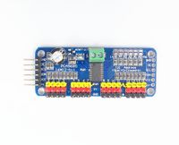 |
Adafruit PCA9685 16 channel PWM controller | PCA9685 | 6.5 € | ||
| 8 | 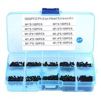 |
set of small screws | set of small screws | 8.5 € | ||
| 9 |  |
12 x MG90S | 12 x MG90s | 42 € | ||
| Total | ~ 135 € | |||||
| a | 
|
Breadbord Kit | MB102 Breadbord Kit | 7 € | ||
| b | 
|
Ulrasound Sensor | 5 x HC-SR04 + Cables | 10 € |
Printing
You might want to make sure that you print your parts with sufficient infill - I used 75%.
Example for broken part
This part was printed with Cura's default infill an broke off:
Assembly
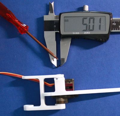
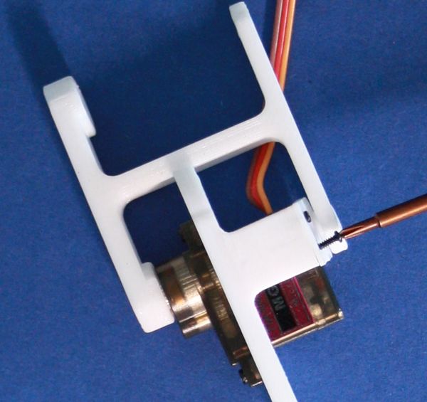
- Legs and hinges are connected with 1.4x5mm screws
- Legs and servos are connected with 1.7x6mm screws
We use the raspberry base from https://github.com/yasaspeiris/aragog/blob/master/3d%20printed%20parts/base.STL
Leg Test
sudo python3 testadafruit.py 0 1 2 3 0
sudo python3 testadafruit.py 0 1 2 3 90
sudo python3 testadafruit.py 0 1 2 3 180
testadafruit.py
# Test Adafruit
# WF 2019-07-09
import sys
import time
from adafruit_servokit import ServoKit
kit = ServoKit(channels=16)

#
# set the given angle for the given servos
#
def setAngle(servos,angle):
  print (angle)
  for id in servos:
    kit.servo[id].angle=angle
  time.sleep(0.3)

# Test Servo Software
servos=[]
args=len(sys.argv)
fromangle=0
toangle=180
step=1
if args>1:
  for port in range(1,args-1,1):
    servos.append(int(sys.argv[port]))
  anglestr=sys.argv[args-1]
  if "-" in anglestr:
    parts=anglestr.split("-")
    fromangle=int(parts[0])
    toangle=int(parts[1])
  else:
    fromangle=int(anglestr)
    toangle=fromangle
else:
  servos.append(0)
  servos.append(1)
  servos.append(2)

if fromangle!=toangle:
  try:
    while True:
      for setangle in range(fromangle,toangle+step,step):
        setAngle(servos,setangle)
  except KeyboardInterrupt:
    print("Keyboard interrupt")
else:
  setAngle(servos,fromangle)
Evolution of Base
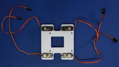
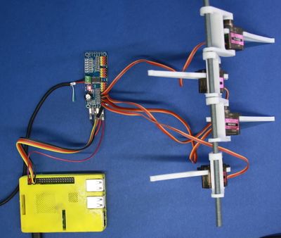
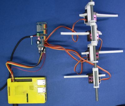
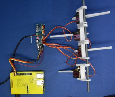
Since we'd like to use a Raspberry PI we couldn't use the orignal Base by regishu. Trying the one from https://github.com/yasaspeiris/aragog also did not work since our raspberry PI case hat a different size. So incrementally a new design was created:
Legtest 2
The three parts of a leg have been connected to the ports 10,11 and 12 and then the test was started with:
sudo python3 testadafruit.py 10 11 12 60-120
<HTML5video width="960" height="600" controls autoplay="false" loop="false">legtest2019-07-25</HTML5video>
