Difference between revisions of "Raspberry PI Spiderbot"
(→Links) |
|||
| (29 intermediate revisions by the same user not shown) | |||
| Line 1: | Line 1: | ||
| + | {{OsProject | ||
| + | |id=PI-Q-Robot | ||
| + | |owner=BITPlan | ||
| + | |title=Raspberry PI controlled Quadruped Robot with 3D Simulator | ||
| + | |url=https://github.com/BITPlan/PI-Q-Robot | ||
| + | |version=0.0.1 | ||
| + | |date=2019-08-07 | ||
| + | }} | ||
Inspired by the Arduino Project below we'd like to create a Raspberry PI version as in https://github.com/yasaspeiris/aragog | Inspired by the Arduino Project below we'd like to create a Raspberry PI version as in https://github.com/yasaspeiris/aragog | ||
= Video = | = Video = | ||
<youtube>fiQbOWvqVco</youtube> | <youtube>fiQbOWvqVco</youtube> | ||
| + | = Simulator = | ||
| + | * http://pi-q-robot.bitplan.com/ | ||
| + | * {{Link|target=PI-Q-Robot|title=Simulator documentation}} | ||
| + | |||
= Links = | = Links = | ||
* [https://www.thingiverse.com/thing:2204279 Spider robot(quad robot, quadruped)-MG90 regishu 2017] | * [https://www.thingiverse.com/thing:2204279 Spider robot(quad robot, quadruped)-MG90 regishu 2017] | ||
| + | * https://github.com/regishsu/SpiderRobot | ||
* https://www.hackster.io/yasaspeiris/raspberry-pi-powered-quadruped-bbb68b | * https://www.hackster.io/yasaspeiris/raspberry-pi-powered-quadruped-bbb68b | ||
| + | * https://github.com/yasaspeiris/aragog | ||
| + | == Other == | ||
| + | * https://github.com/topics/quadruped | ||
| + | * https://github.com/anoochit/arduino-quadruped-robot | ||
| + | |||
= Parts = | = Parts = | ||
| − | + | {| class="wikitable" | |
| − | + | |- | |
| − | + | ! # !! picture !! part !! example sources !! documents !! ~ price | |
| − | + | |- | |
| − | [[File:SpiderBotParts-IMG_0028.jpeg|400px]] | + | | 1 || [[File:713LX1Z383L. SL1500 .jpg|200px]] || Raspberry PI 3 B+ || [https://www.amazon.de/Raspberry-1373331-Pi-Modell-Mainboard/dp/B07BDR5PDW Raspberry PI 3 B+] || [https://www.raspberrypi.org/documentation/hardware/computemodule/datasheets/rpi_DATA_CM3plus_1p0.pdf en] || 35 € |
| + | |- | ||
| + | | 2 || [[File:81UBu4aoQHL. SL1500 .jpg|200px]] || microSD Card || [https://www.amazon.de/dp/B073S9SFK2/ SanDisk 16 GB] || || 7 € | ||
| + | |- | ||
| + | | 3 || [[File:61Z5yEYfnAL. SL1426 .jpg|200px]] || Raspberry PI Camera || [https://www.amazon.de/Raspberry-Pi-V2-1-1080P-Kamera-Modul/dp/B01ER2SKFS 1080 p Camera Module] || || 23 € | ||
| + | |- | ||
| + | | 4 || [[File:41smcErJNjL.jpg|200px]] || DC/DC Converter 12 V-> 5V || [https://www.amazon.de/riorand-Display-Netzteil-Converter-Modul/dp/B00G890MIC 12 V->5 V Converter Module] || || 7 € | ||
| + | |- | ||
| + | | 5 || [[File:31pzC7A3D3L.jpg|200px]] || Micro USB Connector || [https://www.amazon.de/Delock-Stecker-Offene-Kabelenden-schwarz/dp/B01A9GLG6Q Delock USB 2.0 Micro USB] || || 6 € | ||
| + | |- | ||
| + | | 6 || [[File:SpiderBot-Parts-IMG_0033.JPG|200px]] || 3D Printed Parts: Coxa, Tibia, Femur, Hinge || [https://www.thingiverse.com/thing:2204279 parts from regishu's design] || || | ||
| + | |- | ||
| + | | 7 || [[File:61B2dK96ysL. SL1000 .jpg|200px|link=https://www.amazon.de/PCA9685-Servomotor-Treiber-Arduino-Roboter/dp/B06XSFFXQY]] || Adafruit PCA9685 16 channel PWM controller || {{Link|target=PCA9685}} || || 6.5 € | ||
| + | |- | ||
| + | | 8 || [[File:61yfILxEkgL._SX679_.jpg|200px]] || set of small screws || [https://www.amazon.de/gp/product/B07LFDDXZ2 set of small screws] || || 8.5 € || | ||
| + | |- | ||
| + | | 9 || [[File:71a1K3RQuqL. SX679 .jpg|200px]] || 12 x MG90S || [https://www.amazon.de/gp/product/B07FQMTLD4 12 x MG90s] || || 42 € | ||
| + | |- | ||
| + | | || || || ||Total || ~ 135 € | ||
| + | |- | ||
| + | | a | ||
| + | | [[File:71AYEqpWHcL. SL1500 .jpg|200px]] | ||
| + | | Breadbord Kit | ||
| + | | [https://www.amazon.de/gp/product/B01N4VCYUK MB102 Breadbord Kit] | ||
| + | | | ||
| + | | 7 € | ||
| + | |- | ||
| + | | b | ||
| + | | [[File:714Ep9LpwoL. SL1200 .jpg | 200 px]] | ||
| + | | Ulrasound Sensor | ||
| + | | [https://www.amazon.de/gp/product/B01M9CMJ9O 5 x HC-SR04 + Cables] | ||
| + | | | ||
| + | | 10 € | ||
| + | |} | ||
| + | = Printing = | ||
| + | You might want to make sure that you print your parts with sufficient infill - I used 75%. | ||
| + | |||
| + | [[File:SpiderBotParts-IMG_0028.jpeg|960px]] | ||
| + | == Example for broken part == | ||
| + | This part was printed with {{Link|target=Cura}}'s default infill and broke off: | ||
| + | |||
| + | [[File:Broken-IMG_0034.JPG|400px]] | ||
= Assembly = | = Assembly = | ||
| Line 16: | Line 75: | ||
* Legs and servos are connected with 1.7x6mm screws | * Legs and servos are connected with 1.7x6mm screws | ||
[[File:Leg_IMG_0029.JPG|400px]] | [[File:Leg_IMG_0029.JPG|400px]] | ||
| − | [[File:LegConnection-IMG_0030.JPG]] | + | [[File:LegConnection-IMG_0030.JPG|600px]] |
| + | |||
| + | We use the raspberry base from https://github.com/yasaspeiris/aragog/blob/master/3d%20printed%20parts/base.STL | ||
| + | |||
| + | [[File:Plate-IMG_0033.JPG|400px]] | ||
| + | |||
= Leg Test = | = Leg Test = | ||
<source lang='bash'> | <source lang='bash'> | ||
| Line 77: | Line 141: | ||
setAngle(servos,fromangle) | setAngle(servos,fromangle) | ||
</source> | </source> | ||
| + | |||
| + | = Evolution of Base = | ||
| + | Since we'd like to use a Raspberry PI we couldn't use the orignal Base by regishu. Trying the one from https://github.com/yasaspeiris/aragog also did not work since our raspberry PI case had a different size. So incrementally a new design was created: | ||
| + | |||
| + | [[File:Evolution_of_Base_IMG_0030.JPG|800px]] | ||
| + | |||
| + | The problems mentioned further below led to this design: | ||
| + | |||
| + | [[File:Modified_Base-IMG_0036.JPG|400px]] | ||
| + | |||
| + | = Legtest 2= | ||
| + | The three parts of a leg have been connected to the ports 10,11 and 12 and then the test was started with: | ||
| + | <source lang='bash'>sudo python3 testadafruit.py 10 11 12 60-120</source> | ||
| + | <HTML5video width="960" height="600" controls autoplay="false" loop="false">legtest2019-07-25</HTML5video> | ||
| + | |||
| + | = Wiring = | ||
| + | Breadboard - style wiring before designing a proper holder: | ||
| + | |||
| + | [[File:Wiring-IMG_0035.JPG|960px]] | ||
| + | |||
| + | In this state of affairs: | ||
| + | # the power input of the raspberry is blocked by a servo - needs to be moved by at least 13 mm | ||
| + | # the corner hinges are to close to the corners of the servo holders | ||
| + | # the pivots to be used for the next level are blocking e.g. the usb connectors | ||
= What Links Here = | = What Links Here = | ||
{{WhatLinksHere}} | {{WhatLinksHere}} | ||
[[Category:Raspberry]] | [[Category:Raspberry]] | ||
Revision as of 10:18, 17 August 2019
| OsProject | |
|---|---|
| id | PI-Q-Robot |
| state | |
| owner | BITPlan |
| title | Raspberry PI controlled Quadruped Robot with 3D Simulator |
| url | https://github.com/BITPlan/PI-Q-Robot |
| version | 0.0.1 |
| description | |
| date | 2019-08-07 |
| since | |
| until | |
Inspired by the Arduino Project below we'd like to create a Raspberry PI version as in https://github.com/yasaspeiris/aragog
Video
Simulator
Links
- Spider robot(quad robot, quadruped)-MG90 regishu 2017
- https://github.com/regishsu/SpiderRobot
- https://www.hackster.io/yasaspeiris/raspberry-pi-powered-quadruped-bbb68b
- https://github.com/yasaspeiris/aragog
Other
Parts
| # | picture | part | example sources | documents | ~ price | |
|---|---|---|---|---|---|---|
| 1 |  |
Raspberry PI 3 B+ | Raspberry PI 3 B+ | en | 35 € | |
| 2 |  |
microSD Card | SanDisk 16 GB | 7 € | ||
| 3 |  |
Raspberry PI Camera | 1080 p Camera Module | 23 € | ||
| 4 |  |
DC/DC Converter 12 V-> 5V | 12 V->5 V Converter Module | 7 € | ||
| 5 |  |
Micro USB Connector | Delock USB 2.0 Micro USB | 6 € | ||
| 6 |  |
3D Printed Parts: Coxa, Tibia, Femur, Hinge | parts from regishu's design | |||
| 7 | 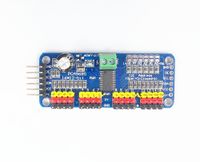 |
Adafruit PCA9685 16 channel PWM controller | PCA9685 | 6.5 € | ||
| 8 |  |
set of small screws | set of small screws | 8.5 € | ||
| 9 |  |
12 x MG90S | 12 x MG90s | 42 € | ||
| Total | ~ 135 € | |||||
| a | 
|
Breadbord Kit | MB102 Breadbord Kit | 7 € | ||
| b | 
|
Ulrasound Sensor | 5 x HC-SR04 + Cables | 10 € |
Printing
You might want to make sure that you print your parts with sufficient infill - I used 75%.

Example for broken part
This part was printed with Cura's default infill and broke off:

Assembly
- Legs and hinges are connected with 1.4x5mm screws
- Legs and servos are connected with 1.7x6mm screws


We use the raspberry base from https://github.com/yasaspeiris/aragog/blob/master/3d%20printed%20parts/base.STL

Leg Test
sudo python3 testadafruit.py 0 1 2 3 0

sudo python3 testadafruit.py 0 1 2 3 90

sudo python3 testadafruit.py 0 1 2 3 180

testadafruit.py
# Test Adafruit
# WF 2019-07-09
import sys
import time
from adafruit_servokit import ServoKit
kit = ServoKit(channels=16)

#
# set the given angle for the given servos
#
def setAngle(servos,angle):
  print (angle)
  for id in servos:
    kit.servo[id].angle=angle
  time.sleep(0.3)

# Test Servo Software
servos=[]
args=len(sys.argv)
fromangle=0
toangle=180
step=1
if args>1:
  for port in range(1,args-1,1):
    servos.append(int(sys.argv[port]))
  anglestr=sys.argv[args-1]
  if "-" in anglestr:
    parts=anglestr.split("-")
    fromangle=int(parts[0])
    toangle=int(parts[1])
  else:
    fromangle=int(anglestr)
    toangle=fromangle
else:
  servos.append(0)
  servos.append(1)
  servos.append(2)

if fromangle!=toangle:
  try:
    while True:
      for setangle in range(fromangle,toangle+step,step):
        setAngle(servos,setangle)
  except KeyboardInterrupt:
    print("Keyboard interrupt")
else:
  setAngle(servos,fromangle)
Evolution of Base
Since we'd like to use a Raspberry PI we couldn't use the orignal Base by regishu. Trying the one from https://github.com/yasaspeiris/aragog also did not work since our raspberry PI case had a different size. So incrementally a new design was created:

The problems mentioned further below led to this design:

Legtest 2
The three parts of a leg have been connected to the ports 10,11 and 12 and then the test was started with:
sudo python3 testadafruit.py 10 11 12 60-120
Wiring
Breadboard - style wiring before designing a proper holder:

In this state of affairs:
- the power input of the raspberry is blocked by a servo - needs to be moved by at least 13 mm
- the corner hinges are to close to the corners of the servo holders
- the pivots to be used for the next level are blocking e.g. the usb connectors